Magnetic Torque and Moment
Torque on a Loop of Wire
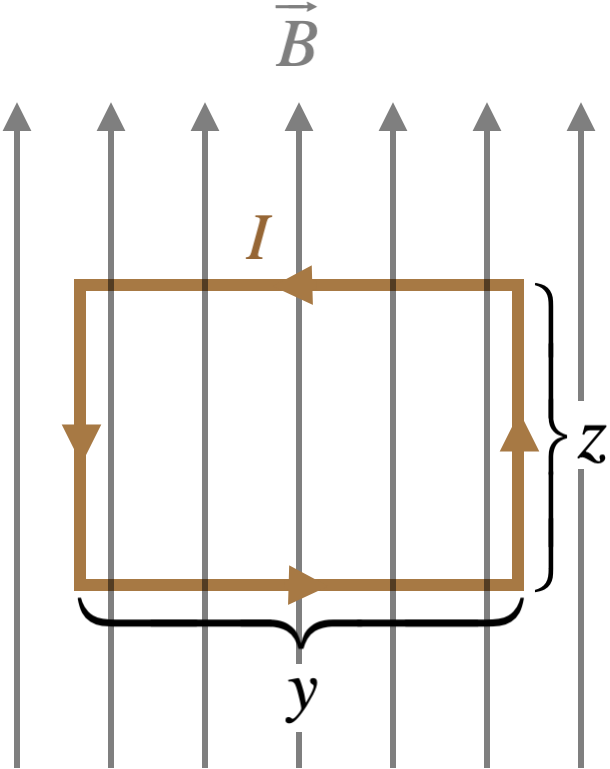
Let’s use our result for the force on a segment of wire to analyze the case of the effect of a magnetic field on a closed loop of wire. We will choose a simple geometry for this analysis – a rectangular loop of wire with two sides parallel to a uniform magnetic field.
Here are the main features of this set-up:
-
The vertical sides of the rectangular loop are parallel to the magnetic field, so the force on every element is zero, adding up to a total of zero force on each of those sides.
-
The horizontal sides of the rectangular loop are perpendicular to the field, so the sine of the angle that appears in the cross-product is exactly equal to one.
-
The magnetic field is uniform, and the current doesn’t change direction, so combining this with the previous observation, we get a force on each of these segments equal to the same value: $IyB$.
-
We can work out the directions of the forces on these two segments in two ways: Using the right-hand-rule, or plugging-in the unit vectors for the directions of the current and magnetic field, and computing the cross-product. Doing so reveals that the force on the top segment is into the page, while the force on the bottom segment is out of the page.
The forces on the horizontal segments cancel, resulting in zero net force on the loop, but of course there is a net torque. Choosing an axis that is a horizontal line passing through the centers of the two vertical segments, we can compute the net torque on the loop. Choosing the positive torque direction to be to the left, the forces on top and bottom both generate torques in that positive direction, so: \(\tau_{net} = F_{top}\left(\dfrac{z}{2}\right) + F_{bottom}\left(\dfrac{z}{2}\right) = 2\left(IyB\right)\left(\dfrac{z}{2}\right) = I\left(yz\right)B\)
Magnetic Dipole Moment
Here we introduce a shortcut for future torque calculations. The
quantity $yz$ is the area of the loop, $A$. In future applications, we
may have the current fed into the loop by a single wire, which is wound
around the perimeter several times. The force exerted on each side of
the loop (and therefore the torque) will then be multiplied by the
number of turns in the wire, $N$. The product of $N$, $I$, and $A$ is
written as a single quantity $\mu$, giving the magnitude of the torque
for this case the simple form of $\tau=\mu B$.
If this loop turns upon its axis, then the moment arm shrinks. For
example, if the top of the loop rotates back and the bottom rotates
forward by $90^\circ$, then the forces on those segments will be
directly away from each other. These forces act straight through the
axis, so the torque they produce is zero. We know that torque and
magnetic field are both vectors, and the torque created is related to
the orientation of the loop in the field. We can account for the loop
orientation by defining a magnetic dipole moment:
\(\overrightarrow \mu \equiv NI\overrightarrow A\) The vector $\vec{A}$
has a magnitude equal to the area of the loop, and has a direction that
is perpendicular to the plane of the loop, in the direction defined as
follows: Curl the fingers of your right hand in a direction that traces
the direction of the current around the loop, and the thumb of that hand
points the direction of the vector. The torque vector can now be
calculated from the magnetic dipole moment in the same way that the
torque exerted on an electric dipole was calculated:
\(\overrightarrow\tau_{electric} = \overrightarrow p \times \overrightarrow E \;\;\;\Leftrightarrow\;\;\; \overrightarrow\tau_{magnetic} = \overrightarrow \mu \times \overrightarrow B\)